|
|
|
Nation: |
USA |
|
Manufacturer: |
General Dynamics Corp, Lockheed Martin |
|
Type: |
multirole class A fighter |
|
Year: |
Winner of competention February 1972
Firts prototype (s/n 72-01567) started 13th December 1973
Second prototype YF-16 (s/n 72-01568) started 9th May 1974
Until January 1975, 11 F-16A, 4 F-16B
Officially chosen 7th June 1975
First definitive model F-16A flown 8th Decemder 1976
First definitive model F-16B flown 8th August 1977 |
|
Engine: |
F-16A/B: one Pratt and Whitney F100-PW-200.
F-16A/B: one Pratt and Whitney F100-PW-220E.
F-16C/D: one Pratt and Whitney F100-PW-200/220/229 or General
Electric F110-GE-100/129 SOUND |
|
Thrust: |
F-16A/B, 23,830 pounds(10,794 kilograms)
F-16A/B MLU, 23770 pounds (10,767 kilograms)
F-16C/D, 27,000 pounds(12,150 kilograms) |
|
Versions: (Detailed) |
|
A,B |
C,D |
|
31 ft (9.45 m) |
32 ft, 8 in (9.8 m) |
|
47 ft 8 in (14.52 m) |
49 ft, 5 in (14.8 m) |
|
16 ft 5 in (5.01 m) |
16 ft (4.8 m) |
|
|
3.2 |
|
|
18 ft 31 in (5.58 m ) |
|
|
7 ft 9 in (2.36 m) |
|
|
13 ft 11 in (4 m) |
|
|
Wingspan: (over
missile launchers) |
|
Lenght: |
|
Height: |
|
Wing aspect ratio |
|
Tailplane span |
|
Whell track |
|
Wheelbase |
|
Weight: |
F-16A/B: 33,000 lb (14,968 kg) /full loaded/
F-16C/D Block 50/52: 42,300 lb (19,187 kg) /full loaded/
F-16C: F100-PW-229/F110-GE-229 ... 8,433 kg (18,591 lb)/8,581
kg (18,917 lb) /empty/
F-16D: F100-PW-229/F110-GE-229 ... 8,645 kg (19,059 lb)/8,809
kg (19,421 lb) /empty/ |
|
Max internal fuel (JP-8) |
F-16C: 3,249 kg (7,162 lb)
F-16D: 2,687 kg (5,924 lb) |
|
Max external fuel (JP-8) |
3,208 kg (7,072 lb) |
|
Maximum takeoff weight: |
37,500 pounds (16,875 kilograms) |
|
Maximum speed: |
1,319 mph (2,123km/h) at 39,370 ft (12,000 m) |
|
Ceiling: |
50,000 ft (15,240 m) |
|
Radius of action: |
676 - 866 n miles (1,252 - 1,604 km) |
|
Ferry range: |
1,961 - 2,276 n miles (3,632 - 4,215 km) |
|
Crew: |
version A, C: 1; B, D: 2 or 1 |
|
Armament: |
General Electric M61A1
20mm six-barrel cannon and two wingtip Sidewinder
or Sparrow air-to-air missiles; nine
additional hardpoints capable of carrying up to 15,200 lbs of
other stores. |
|
Systems: |
AN/APG-66/68 pulsed-Doppler
radar
AN/AAQ-13 LANTIRN NAVIGATION POD
AN/AAQ-14 LANTIRN/SHARPSHOOTER
AN/AAQ-20 PATHFINDER NAVIGATION POD
AN/ASQ-213 HARM TARGETING SYSTEM POD
AN/ALQ-119 ECM POD
AN/ALQ-131 ECM POD
AN/ALQ-178 internal ECM
AN/ALQ-184 ECM POD
AN/ALR-56M threat warning receiver [F-16C/D
Block 50/52]
AN/ALR-69 radar warning system (RWR)
AN/ALR-74 radar warning system (RWR) [replaces AN/ALR-69]
AN/ALE-40 chaff/flare dispenser |
 |
|
|
Features
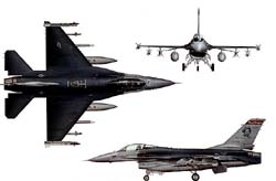
The General Dynamics/Lockheed Martin Fighting
Falcon [ versions ] is considered
by many to be the most agile modern fighter. Less than half the
weight of the F-14,
it carries a larger payload; less than one-fourth the cost of
the F-15, it has superior maneuverability. In addition, advanced
avionics and electronics give it excellent air-to-ground precision.
The F-16 can deliver a crippling ground strike and still maintain
a credible air threat.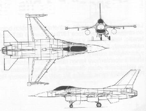
In an air combat role, the F-16's maneuverability and combat
radius (distance it can fly to enter air combat, stay, fight
and return) exceed that of all potential threat fighter aircraft.
It can locate targets in all weather conditions and detect low
flying aircraft in radar ground clutter. In an air-to-surface
role, the F-16 can fly more than 500 miles (860 kilometers),
deliver its weapons with superior accuracy, defend itself against
enemy aircraft, and return to its starting point. An all-weather
capability allows it to accurately deliver ordnance during non-visual
bombing conditions.
In designing the F-16, advanced aerospace
science and proven reliable systems from other aircraft such
as the F-15 and F-111 were selected. These were combined to simplify
the airplane and reduce its size, purchase price, maintenance
costs and weight. The light weight of the fuselage is achieved
without reducing its strength. With a full load of internal fuel,
the F-16 can withstand up to 9 G's -- nine times the force of
gravity -- which exceeds the capability of other current fighter
aircraft.
The cockpit and its bubble canopy give the
pilot unobstructed forward and upward vision, and greatly improved
vision over the side and to the rear. The seat-back angle was
expanded from the usual 13 degrees to 30 degrees, increasing
pilot comfort and gravity force tolerance. The pilot has excellent
flight control of the F-16 through its "fly-by-wire"
system. Electrical wires relay commands, replacing the usual
cables and linkage controls. For easy and accurate control of
the aircraft during high G-force combat maneuvers, a side stick
controller is used instead of the conventional center-mounted
stick. Hand pressure on the side stick controller sends electrical
signals to actuators of flight control surfaces such as ailerons
and rudder.
Avionics systems include a highly accurate
inertial navigation system in which a computer provides steering
information to the pilot. The plane has UHF and VHF radios plus
an instrument landing system. It also has a warning system and
modular countermeasure pods to be used against airborne or surface
electronic threats. The fuselage has space for additional avionics
systems.
All F-16s delivered since November 1981 have
built-in structural and wiring provisions and systems architecture
that permit expansion of the multirole flexibility to perform
precision strike, night attack and beyond-visual-range interception
missions. This improvement program led to the F-16C and F-16D
aircraft, which are the single- and two-place counterparts to
the F-16A/B, and incorporate the latest cockpit control and display
technology. All active units and many Air National Guard and
Air Force Reserve units have converted to the F-16C/D.
The Falcon’s versatility is still being explored. The variety
of stores it can carry and wide range of missions it can undertake
with great effectiveness are staggering. The F-16 has proven
itself capable of air superioority, „Wild Weasel,"
strike, and reconnaissance missions without any structural modofications.
The simple addition of the proper external pods or ordnance is
all that is required. There is even an experimental GPU-5 external
gun pod which contains a 30mm cannon firing the same shells as
the A-10’s famous tank-busting Avenger.
Service Life
The Falcon Up Structural Improvement Program
program incorporates several major structural modifications into
one overall program, affecting all USAF F-16s. Falcon Up will
allow Block 25/30/32 aircraft to meet a 6000 hour service life,
and allow Block 40/42 aircraft to meet an 8000 hour service life.
In view of the challenges inherent in operating F-16s to 8,000
flight hours, together with the moderate risk involved in JSF
integration, the Department has established a program to earmark
by FY 2000 some 200 older, Block 15 F-16 fighter aircraft in
inactive storage for potential reactivation. The purpose of this
program is to provide a basis for constituting two combat wings
more quickly than would be possible through new production. This
force could offset aircraft withdrawn for unanticipated structural
repairs or compensate for delays in the JSF program. Reactivating
older F-16s is not a preferred course of action, but represents
a relatively low-cost hedge against such occurrences.
The Air Force will soon be flying only Block
40/42 and Block 50/52 F-16s in its active-duty units. Block 25
and Block 30/32 will be concentrated in Air National Guard and
Air Force Reserve units.
The Fighting Falcon forms the backdone of the USA - Qty.: 2500+
- US tail code marking
|
USA |
Qty. |
Model/Block (detailed) |
Air Combat Command - ACC
[Tactical Air Command - TAC] |
2230 |
YF16A
FSD
A,B/5
A,B/10
A,B/15
C,D/25
C,D/30
C,D/32
C,D/40
C,D/42
C,D/50
C,D/52 |
|
Air Education and Training Command - AETC |
? |
A,B/20
?/52 |
|
Air Force Materiel Command - AFMC |
? |
A,B/?
D/40
?/50 |
Air Force Reserve Command - AFRC
[Air Force Reserve - AFRES] |
? |
C,D/25
C,D/30
C,D/32 |
|
Air National Guard - ANG |
? |
A,B/15ADF
A,B/15
C,D/25
C,D/30
C,D/42
C,D/52 |
|
United States Air Forces in Europe - USAFE |
? |
C,D/25
C,D/40
C,D/50 |
|
Pacific Air Forces - PACAF |
? |
C,D/40
C,D/42
C,D/50
C,D/52 |
|
US Navy - USN |
40 |
A,B/15OCU
N/30
T-N/30 |
|
National Aeronautics and Space Administration
- NASA |
4 |
A,B/XL
A/AFTI
A/15 |
Deployments:
Desert Storm - Iraq
F-16 was used in the Persian Gulf war of 1991 in larger numbers
than any other fighter, with 249 F-16A's and C's seeing action.
The US ANG had two units flying the F-16A, while all the regular
USAF were flying the C models. Many of the F-16s in Gulf were
Block 40 models. However, since LANTIRN targeting pods were still
in short supply, and since the F-15E force had higher priority,
only 72 of the F-16s used during Desert Storm were fitted with
LANTIRN pods (most of them carrying only the navigation pod).
With out the targeting pod, the three squadrons of block-40's
were unable to drop laser guided bombs. The majority of the F-16
force was forced to fly during daylight hours.
Operation Northern Watch & Operation Southern Watch
Following Desert Storm, a no-fly zone was established over
Iraq in April 1991 and designated Operation Southern Watch. The
no-fly zone was the airspace below the 32nd parallel. At the
same time Operation Southern Watch was initiated Operation Provide
Comfort started in the North. This was an effort to protect the
Kurds which were being slaughtered by Saddam's forces and not
allowed into Turkey. When Provide Comfort ended it was renamed
Operation Northern Watch which began on January 1st, 1997. It
was the 36th parallel that was the line of division for Northern
Watch, all Iraqi airspace north of this parallel. The no-fly
zones were regularly patrolled by the USAF and eventually air
forces of various nations.
Operation Allied Force - Balkan
Even more than in operation Desert Storm, operation Allied
Force was dominated by the F-16. This time not only USAF F-16s
participated, but also F-16s from European air forces. A wide
variety of missions were flown with the F-16 including CAP, strike,
reconnaissance, SEAD, etc. The operation started at 19:00 hr
on March 24th, 1999 and lasted until June 10th.
Noble Eagle
Operation Noble Eagle was a direct
result of the attacks on America on September 11th, 2001.
Operation Enduring Freedom
The offensive against whom was behind the attacks on America
on September 11th, 2001, Taliban - Afghanistan.
Operation Iraqi Freedom
F-16 played a major part in this conflict. Many lessons were
learned for the F-16 from the USAF's many recent operations.
The F-16 was a much more formidable weapon then the last war
in Iraq. The operation began with an air campaign, targeted at
destroying the Iraqi defense capabilities, or what was left of
them.
The F-16 also serves in the air forces of :
|
Country |
Qty. |
Model/Block (detailed) |
Bahrain
Royal Bahraini Air Force - RBAF |
22 |
C,D/40 |
Belgium
Belgian Armed Forces/Air Component - BAF |
160 |
A,B/1
A,B/5
A,B/10
A,B/15
A,B/15OCU |
Chile
Fuerza Aerea de Chile
Chilean Air Force - FACh |
28 |
A,B/20MLU
C,D/50 |
Denmark
Flyvevaben
Royal Danish Air Force - RDAF |
77 |
A,B/1
A,B/5
A,B/10
A,B/15 |
Egypt
Al Quwwat al Jawwiya Ilmisriya
Egyptian Air Force - EAF |
220 |
A,B/15
C,D/32
C,D/40 |
Greece
Elliniki Aeroporia
Hellenic Air Force - HAF |
180 |
C,D/30
C,D/50
C,D/52 |
Indonesia
Tentara Nasional Indonesia-Angkatan Udara
Indonesian Air Force - TNI-AU |
12 |
A,B/15OCU |
Israel
Cheil Ha'avir
Israel Defense Force/Air Force - IDF/AF |
362 |
A,B/1
A,B/5
A,B/10
C,D/30
C,D/40
D/52 |
Italy
Aeronautica Militare Italiana
Italian Air Force - AMI |
34 |
A,B/15ADF
A,B/10
B/5 |
Jordan
Al Quwwat al Jawwiya al Malakiya al Urduniya
Royal Jordanian Air Force - RJAF |
36 |
A,B/15ADF
B/20MLU |
Norway
Luftforsvaret
Royal Norwegian Air Force - RNoAF |
74 |
A,B/1
A,B/5
A,B/10
A,B/15
B/15OCU |
Oman
Al Quwwat al Jawwiya al Sultanat Oman
Royal Air Force of Oman - RAFO |
12 |
C,D/50 |
Pakistan
Pakistan Fiza'ya
Pakistan Air Force - PAF |
111 |
A,B/15OCU
A,B/15 |
Poland
Si³y Powietrzne Rzeczpospolitej Polskiej
Polish Air Force - POLAF |
ord.48 |
C,D/52 |
Portugal
Força Aérea Portuguesa
Portuguese Air Force - PoAF |
45 |
A,B/15OCU
A,B/15 |
Republic of China / Taiwan
Chung-kuo Kung Chun
Republic of China Air Force - RoCAF |
150/30? |
A,B/20
C,D/52? |
Singapore
Republic of Singapore Air Force - RSAF |
70 |
A,B/15OCU
C,D/52 |
South Korea
Han-guk Kong Goon
Republic of Korea Air Force - RoKAF |
180 |
C,D/32
C,D/52 |
Thailand
KongTup Arkard Thai
Royal Thai Air Force - RTAF |
54 |
A/10OCU
A,B/15OCU
A,B/15ADF |
The
Netherlands
Koninklijke Luchtmacht
Royal Netherlands Air Force - RNlAF |
213 |
A,B/1
A,B/5
A,B/10
A,B/15
A,B/15OCU |
Turkey
Turk Hava Kuvvetleri
Turkish Air Force - TuAF |
240 |
C,D/30
C,D/40
C,D/50 |
United
Arab Emirates
Al Imarat al Arabiyah al Muttahidah
United Arab Emirates Air Force - UAEAF |
80 |
E,F/60 |
Venezuela
Fuerza Aéra Venezolana
Venezuelan Air Force - FAV |
25 |
A,B/15 |
|
|
Design Features |
Structure |
|
Cantilever mid-wing monoplane of blended wing-body
design and cropped delta planform. The blended wing-body concept
is achieved by flaring the wing/body intersection, thus not only
providing lift from the body at highangles of attack but also
giving less wetted area and increased internal fuel volume. Basic
wing is NACA 64A-204 section with 40o sweepback on leading-edges.
The tail unit is a cantilever structure with sweptback surfaces.
Optional extension of fin root fairing houses ECM equipment in
some aircraft and a brake parachute in other aircraft. Ventral
fins three-quarters along fuselage. |
Wing, mainly of aluminium alloy with 11 spars,
five ribs and single upper and lower skins, is attached to fuselage
by machined aluminium fittings. The fuselage is a semi-monocoque
all-metal structure of frames and longerons built in three main
modules: forward (to just aft of cockpit), centre and aft. Nose
radome built by Brunswick corporation.Highly swept vortex control
strakes along the fuselage forebody increase lift and improve
directional stability at high angles of attack. The tail unit
fin is a multispar, multirib
aluminium structure with graphite epoxy skins, aluminium tip
and glass fibre dorsal fin and root fairing. Tailplanes constructed
of graphite epoxy composite laminate skins mechanically attached
to a corrugated aluminium substructure. Each tailplane half has
an aluminium pivot shaft and a removable full-depth bonded honeycomb
leading-edge. Ventral fins are bonded aluminium skins. |
|
|
|
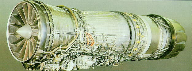
Engine
|
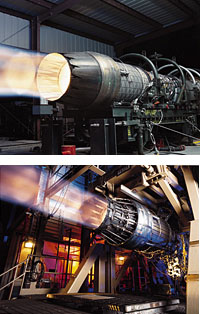
The development of the Pratt & Whitney
F100 turbofan began in August of 1968 when the USAF awarded contracts
to both P & W and General Electric for the development of
engines to be used in the projected F-X fighter, which was later
to emerge as the F-15 Eagle.
In 1970, Pratt and Whitney was declared the winner of the competition
and was awarded the contract for the engine for the F-15. The
engine was to be designated F100. Two versions of the engine
were planned, the F100 for the USAF and the F401 for the Navy.
The latter engine was intended for later models of the F-14
Tomcat, but was cancelled when the size of the planned Tomcat
fleet was cut back in an economy move.
The F100 is an axial-flow turbofan with a bypass ratio of 0.7:1.
There are two shafts, one shaft carrying a three-stage fan driven
by a two-stage turbine, the other shaft carrying the 10-stage
main compressor and its two-stage turbine. For the F100-PW-200
version, normal dry thrust is 12,420 pounds, rising to a maximum
thrust of 14,670 pounds at full military power. Maximum afterburning
thrust is 23,830 pounds.
 The
F100 engine was first tried in service with the F-15 Eagle. The
Air Force had hoped that the F100 engine would be a mature and
reliable powerplant by the time that the F-16 was ready to enter
service. However, there were a protracted series of teething
troubles with the F100 powerplants of the F-15, compounded by
labor problems at two of the major subcontractors. Initially,
the Air Force had grossly underestimated the number of engine
powercycles per sortie, since they had not realized how much
the F-15 Eagle's maneuvering capabilities would result in abrupt
changes in throttle setting. This caused unexpectedly high wear
and tear on the engine, resulting in frequent failures of key
engine components such as first-stage turbine blades. Most of
these problems could be corrected by more careful maintenance
and closer attention to quality control during manufacturing
of engine components. Nevertheless, by the end of 1979, the Air
Force was being forced to accept engineless F-15 airframes until
the problems could be cleared up. The
F100 engine was first tried in service with the F-15 Eagle. The
Air Force had hoped that the F100 engine would be a mature and
reliable powerplant by the time that the F-16 was ready to enter
service. However, there were a protracted series of teething
troubles with the F100 powerplants of the F-15, compounded by
labor problems at two of the major subcontractors. Initially,
the Air Force had grossly underestimated the number of engine
powercycles per sortie, since they had not realized how much
the F-15 Eagle's maneuvering capabilities would result in abrupt
changes in throttle setting. This caused unexpectedly high wear
and tear on the engine, resulting in frequent failures of key
engine components such as first-stage turbine blades. Most of
these problems could be corrected by more careful maintenance
and closer attention to quality control during manufacturing
of engine components. Nevertheless, by the end of 1979, the Air
Force was being forced to accept engineless F-15 airframes until
the problems could be cleared up.
However, the most serious problem with the
F100 in the F-15 was with stagnation stalling. Since the compressor
blades of a jet engine are airfoil sections, they can stall if
the angle at which the airflow strikes them exceeds a critical
value, cutting off airflow into the combustion chamber which
results in a sudden loss of thrust. Such an event is called a
stagnation stall. Stagnation stalls most often occurred during
high angle-of-attack maneuvers, and they usually resulted in
abrupt interruptions of the flow of air through the compressor.
This caused the engine core to lose speed, and the turbine to
overheat. If this condition was not quickly corrected, damage
to the turbine could take place or a fire could occur.
Some stagnation stalls were caused by "hard"
afterburner starts, which were mini-explosions that took place
inside the afterburner when it was lit up. These could be caused
either by the afterburner failing to light up when commanded
to do so by the pilot or by the afterburner actually going out.
In either case, large amounts of unburnt fuel got sprayed into
the aft end of the jetpipe, which were explosively ignited by
the hot gases coming from the engine core. The pressure wave
from the explosion then propagated forward through the duct to
the fan, causing the fan to stall and sometimes even causing
the forward compressor stage to stall as well. These types of
stagnation stalls usually occurred at high altitudes and at high
Mach numbers.
Normal recovery technique from stagnation
stalls was for the pilot to shut the engine down and allow it
to spool down. A restart attempt could be made as soon as the
turbine temperature dropped to an acceptable level.
When it first flew, the YF-16 seemed to be
almost free of the stagnation stall problems which had bedeviled
the F-15. However, while flying with an early model of the F100
engine, one of the YF-16s did experience a stagnation stall,
although it occurred outside the normal performance envelope
of the aircraft. Three other incidents later occurred, all of
them at high angles of attack during low speed flights at high
altitude. The first such incident in a production F-16 occurred
with a Belgian aircraft flying near the limits of its performance
envelope. Fortunately, the pilot was able to get his engine restarted
and land safely. The F-16 was fitted with a jet-fuel starter,
and from a height of 35,000 feet the pilot would have enought
time to attempt at least three unassisted starts using ram air.
When the F100 engine control system was originally
designed, Pratt & Whitney engineers had allowed for the possibility
that the ingestion of missile exhaust might stall the engine.
A "rocket-fire" facility was designed into the controls
to prevent this from happening. When missiles were fired, an
electronic signal was sent to the unified fuel control system
which supplied fuel to the engine core and to the afterburner.
This signal commanded the angle of the variable stator blades
in the engine to be altered to avoid a stall, while the fuel
flow to the engine was momentarily reduced and the afterburner
exhaust was increased in area to reduce the magnitude of any
pressure pulse in the afterburner. Tests had shown that this
"rocket-fire" facility was not needed for its primary
purpose of preventing missile exhaust stalls, but it turned out
to be handy in preventing stagnation stalls. Engine shaft speed,
turbine temperature, and the angle of the compressor stator blades
are continuously monitored by a digital electronic engine control
unit which fine-tunes the engine throughout flight to ensure
optimal performance. By monitoring and comparing spool speeds
and fan exhaust temperature, the unit is able to sense that a
stagnation stall is about to occur and send a dummy "rocket-fire"
signal to the fuel control system to initiate the anti-stall
measures described above. At the same time, the fuel control
system reduces the afterburner setting to help reduce the pressure
within the jetpipe.
The afterburner-induced stalls were addressed
by a different mechanism. In an attempt to prevent pulses from
coming forward through the fan duct, a "proximate splitter"
was developed. This is a forward extension of the internal casing
which splits the incoming air from the compressor fan and passes
some of this air into the core and diverts the rest down the
fan duct and into the afterburner. By closing the the gap between
the front end of this casing and the rear of the fan to just
under half an inch, the designers reduced the size of the path
by which high-pressure pulses from the burner had been reaching
the core. Engines fitted with the proximate splitter were tested
in the F-15, but this feature was not introduced on the F-15
production line, since the loss of a single engine was less hazardous
in a twin-engined aircraft like the Eagle. However, this feature
was adopted for the single-engined F-16.
These engine fixes produced a dramatic improvement
in reliability. Engines fitted to the F-16 fleet (and incorporating
the proximate splitter) had only 0.15 stagnation stalls per 1000
hours of flying time, much better than the F-15 fleet.
In recent years, the USAF became interested
in acquiring an alternative engine for the F-16, partly in a
desire to set up a competitive process between rival manufacturers
in an attempt to keep costs down, as well as to develop a second
source of engines in case one of the suppliers ran into problems.
In search of a source for an alternate engine for the F-16 and
for the Navy's F-14 Tomcat, in 1984 the Department of Defense
awarded General Electric a contract to build a small number of
F101 Derivative Fighter Engines (DFE) for flight test. The DFE
was based on the F101 used in the B-1 but incorporated components
derived from the F404 engine used in the F/A-18. The Navy decided
to adopt the DFE as a replacement for the Tomcat's TF30 turbofan,
but the USAF announced that they were going to split future engine
purchases between Pratt & Whitney and General Electric. GE
was given a contract for full-scale development of its new engine,
which was to be designated F110.
 The
General Electric F110 is similar in size to the Pratt & Whitney
F100. The F110 has a three-stage fan leading to a nine-stage
compressor, the first three stages of which are variable. The
bypass ratio is 0.87 to 1. The annular combustion chamber is
designed for smokeless operation, and has 20 dual-cone fuel injectors
and swirling-cup vaporizers. The single-stage HP turbine is designed
to cope with inlet temperatures as high as 2500 degrees F (1370
C). Blades are individually replaceable without rotor disassembly.
An uncooled two-stage LP turbine leads to a fully-modulated afterburner.
When afterburning is demanded, fuel is injected into both the
fan and core flows, which mix prior to combustion. The
General Electric F110 is similar in size to the Pratt & Whitney
F100. The F110 has a three-stage fan leading to a nine-stage
compressor, the first three stages of which are variable. The
bypass ratio is 0.87 to 1. The annular combustion chamber is
designed for smokeless operation, and has 20 dual-cone fuel injectors
and swirling-cup vaporizers. The single-stage HP turbine is designed
to cope with inlet temperatures as high as 2500 degrees F (1370
C). Blades are individually replaceable without rotor disassembly.
An uncooled two-stage LP turbine leads to a fully-modulated afterburner.
When afterburning is demanded, fuel is injected into both the
fan and core flows, which mix prior to combustion.
All F110s ordered by the USAF were for the F-16 fleet, with the
F-15 retaining the F100. The choice of engines for the Fighting
Falcon began with the Fiscal Year 1985 Block 30 F-16C/Ds. About
75 percent of the F-16s purchased from that time on by the USAF
were powered by the GE engine, with the remainder being powered
by the P & W engine. However, it is not intended that individual
units operate with F-16s powered by two different engine types,
since that would create a spare parts and logistics nightmare.
The choice of engines for the F-16 is made at the Wing level.
In an attempt to address some of the reliability problems of
its engine, Pratt & Whitney developed the -220 model of its
F100 turbofan. It has the same thrust as the -200, but is much
more reliable, having improvements which radically lowered the
number of. unscheduled engine shutdowns. Many older -200 engines
were rebuilt to the -220E standard, becoming directly interchangeable
with new-build -220 engines.
In an attempt to make the F100 more competitive with the General
Electric F110, Pratt & Whitney introduced the more powerful
F100-PW-229 version in the early 1990s. This engine is rated
at 29,100 pounds of thrust with full afterburner. It has a higher
fan airflow and pressure ratio, a higher-airflow compressor with
an extra stage, a new float-wall combustor, higher turbine temperatures,
and a redesigned afterburner. It has about 22 percent more thrust
than previous F100 models. The first F-16s powered by the -229
engines began to be delivered in 1992. However, the degree of
mechanical changes introduced in the -229 make it impractical
to rebuild -200 or -220E engines to -229 standards.
On the export market, the higher thrust of
the F110 made it the engine of choice through the mid to late
1980s. The more powerful F100-PW-229 finally gave P&W the
chance of re-entering the export market. In 1991, South Korea
chose the F100-PW-229 for its license-built F-16s, maintaining
engine commonality with F-16Cs and Ds that were purchased earlier
from the USA.
The F100-PW-200+ is intended for foreign air
forces which operate significant numbers of F-16s that are powered
by -200 and -220E engines, but which are denied access to the
more powerful -229. It combines the core of the -220 with the
fan, nozzle, and digital control system of the -229. It develops
around 27,000 pounds of thrust with afterburning.
|
|
Flying Controls
/ Cockpit
|
 Leading-edge
manoeuvring flaps are programmed automatically as a function
of Mach number and angle of attack. The increased wing camber
maintains lift co-efficients at high angles of attack. These
flaps are one-piece bonded aluminium honeycomb sandwich structures
actuated by a Garrett drive system using rotary actuators. The
trailing-edges carry large flaperons (flap/ailerons), which are
interchangeable left with right and are actuated by National
Water Lift integrated servo-actuators. The maximum rate of flaperon
movement is 80o/s. Interchangeable, all-moving tailplane halves.
Split speed-brake inboard of rear portion of each horizontal
tail surface to each side of nozzle, each deflecting 60o from
the closed position. National Water Lift servo-actuators for
rudder and tailplane. Leading-edge
manoeuvring flaps are programmed automatically as a function
of Mach number and angle of attack. The increased wing camber
maintains lift co-efficients at high angles of attack. These
flaps are one-piece bonded aluminium honeycomb sandwich structures
actuated by a Garrett drive system using rotary actuators. The
trailing-edges carry large flaperons (flap/ailerons), which are
interchangeable left with right and are actuated by National
Water Lift integrated servo-actuators. The maximum rate of flaperon
movement is 80o/s. Interchangeable, all-moving tailplane halves.
Split speed-brake inboard of rear portion of each horizontal
tail surface to each side of nozzle, each deflecting 60o from
the closed position. National Water Lift servo-actuators for
rudder and tailplane.
|
|

1.LANDING
GEAR HANDLE
moving the gear handle up retracts the landing gear once the
aircraft is airborn.
2.AOA(Angle of Attack) Indicator
The AOA indicator is an instrument that shows the angle of attack
of the aircraft. In order to genirate lift, the jet needs to
have a positive angle of attack or fly at a positive angle into
the relative wind (airflow).
3.Airspeed Indicator
The airspeed indicator shows the aircraft's airspeed in hundreds
of knots. when the red needle is on the "4", you going
400 knots.
4.MDF (Multi Functional Displays)
Two displays on either side of the centre console in the cokpit
that can show all radar modes including combat and navigation,
as well as other vital information.
5.THREAT WARNING SYSTEM
This system detects radar contacting your aircraft and detemines
its type, strength and bearing. |
6. HUD (heads-up-display)
A glass panel in front of the cockpit that shows important navigation
and weapons information.
7.ICP (Integrated Control Panel)
Panel used for weapons release, landing, navigation and Communications.
8. Oil Pressure Indicator
The Oil pressure indocator dipsays engine oil pressure, ranging
from 0 to 100 psi (pounds per squar inch).
9.RPM (Revolutions Per Minute) Indicator
The RPM indicator displays the engine revolutions per minute.
RPM is expressed as a percentage from 0% to 100%
10. Nozzle Position Indocator
This instrument dispalys the position of the engine nozzle.
the indicator wil be mostly open at at idle, closed at Mil power
(100% thrust), and fully open at full afther burner.
11. VVI (Vertical Velocity Indicator)
The vertical Velocity Indicator is an instrument that shows your
rate of climb or descent in feet per minute.
12. ADI(Attitude Direction Indicator)
The instrument that displays the aircraft pitch and control.
13. CONTROLSTICK:
The F-16C/F users "fly-by-wire" Technolgy on an F16
the stick does not control cables that are linked to the surface,
but tather inputs to a computer which in turn controls servos
or hydaulics for the flaps and rudder, ect...
14. HIS (Horizontal Situation Indocator)
The HSI is a round moving dial that shows the aircraft's compass
heading. When the aircraft turns, the dial moves to indicate
the change in aircraft heading.
15. ALTIMETER
The altimete shows the height of the aircraft sbove MSL(Mean
Sea Level)
16. Eject Handle
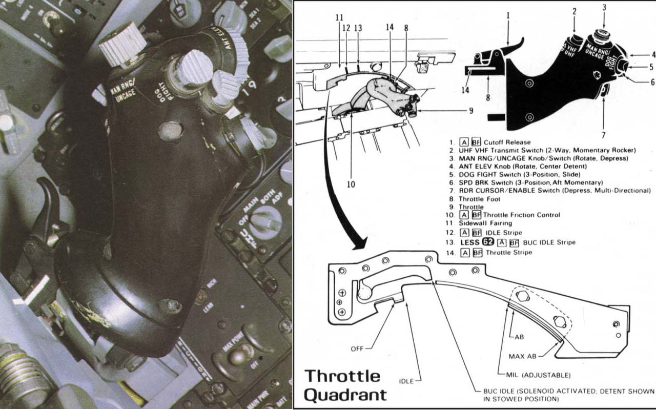
17. Trottle |
|
 |
Cockpit of F16A |
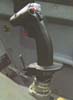
Stick |
 |
Cockpit of F16C |
 |
Cocpkit of F16A |
Throttle quadrant |
 |
HUD F16 C/D and F16 A |
|
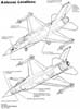
Antenna locations |

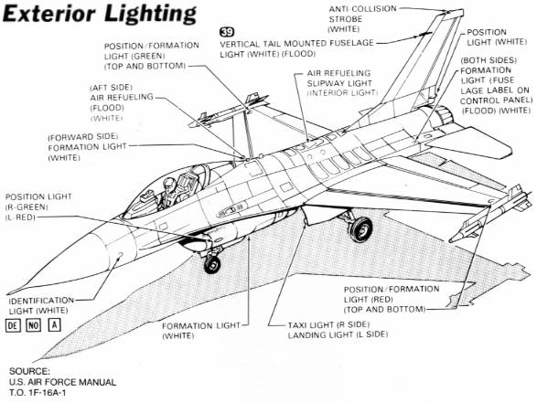
Exterior lighting |
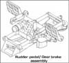
Pedals |
|

F-16A cockpit schema |
|
|
EXPLOSIVE
FRACTURING OF AN F-16 CANOPY FOR THROUGH-CANOPY CREW EGRESS
Laurence J. Bement NASA Langley
Research Center Presented at the The 38th Annual SAFE Symposium
October 9-11, 2000 Reno, Nevada
ABSTRACT
 Through-canopy
crew egress, such as in the Harrier (AV-8B) aircraft, expands
escape envelopes by reducing seat ejection delays in waiting
for canopy jettison. Adverse aircraft attitude and reduced forward
flight speed can further increase the times for canopy jettison.
However, the advent of heavy, high-strength polycarbonate canopies
for bird-strike resistance has not only increased jettison times,
but has made seat penetration impossible. The goal of the effort
described in this paper was to demonstrate a method of explosively
fracturing the F-16 polycarbonate canopy to allow through-canopy
crew ejection. The objectives of this effort were to: Through-canopy
crew egress, such as in the Harrier (AV-8B) aircraft, expands
escape envelopes by reducing seat ejection delays in waiting
for canopy jettison. Adverse aircraft attitude and reduced forward
flight speed can further increase the times for canopy jettison.
However, the advent of heavy, high-strength polycarbonate canopies
for bird-strike resistance has not only increased jettison times,
but has made seat penetration impossible. The goal of the effort
described in this paper was to demonstrate a method of explosively
fracturing the F-16 polycarbonate canopy to allow through-canopy
crew ejection. The objectives of this effort were to:
- Mount the explosive materials on the exterior
of the canopy within the mold line,
- Minimize visual obstructions,
- Minimize internal debris on explosive activation,
- Operate within less than 10 ms,
- Maintain the shape of the canopy after functioning
to prevent major pieces from entering the cockpit, and
- Minimize the resistance of the canopy to
seat penetration.
All goals and objectives were met in a full-scale
test demonstration. In addition to expanding crew escape envelopes,
this canopy fracture approach offers the potential for reducing
system complexity, weight and cost, while increasing overall
reliability, compared to current canopy jettison approaches.
To comply with International Traffic in Arms
Regulations (ITAR) and permit public disclosure, this document
addresses only the principles of explosive fracturing of the
F-16 canopy materials and the end result. ITAR regulations restrict
information on improving the performance of weapon systems. Therefore,
details on the explosive loads and final assembly of this canopy
fracture approach, necessary to assure functional performance,
are not included.
INTRODUCTION
Many current fighter aircraft use canopy jettison
approaches to clear an uninhibited path for crew egress. This
approach uses pyrotechnic (explosive or propellant-actuated)
devices to first activate latch release mechanisms to free the
canopy assembly from the airframe, and then jettison the assembly
with piston/cylinder thrusters or small rocket motors mounted
at the forward edge of the assembly. The canopy pivots around
aft hinge points. Seat ejection catapults are not initiated until
the canopy has pivoted far enough to insure that the seat and
canopy will not collide. How quickly the canopy assembly is jettisoned
depends on aircraft attitude and forward velocity. A pitch-down
attitude with a flight vector to produce a load on the canopy
would resist jettison. Also, if the aircraft has a low forward
velocity, there would be a minimal aerodynamic assist on the
canopy. Some aircraft, such as the F-15, employ a backup approach
to canopy jettison by using frangible acrylic canopies and designing
the seat to "punch through" to insure egress. The Harrier
(AV-8B) aircraft, a vertical takeoff and landing aircraft, utilizes
an interior-mounted explosive cord to fracture acrylic canopies
to assure an immediately available, unrestricted through-canopy
egress path to reduce crew ejection time. However, on activation,
this explosive cord creates explosive pressure waves and peppers
the crew with highvelocity fragments from the explosive's metal
sheath and from the 3/8th-inch width explosive holder. The crewmembers
also face potential harm from the fractured pieces of canopy
material. Canopy jettison approaches introduce a higher degree
of complexity over through-canopy egress. The advent of using
polycarbonate canopies to resist bird strikes eliminated the
possibility of either "punching through" the canopy
or applying the Harrier approach. However, current projections
of thickness and weight of these canopies indicate that thrusters
and rocket motor jettison approaches are reaching capability
limits. Furthermore, canopy release and jettison approaches require
3 to 4 mechanisms, such as latch actuators, thrusters and rocket
motors. For redundancy, each of these mechanisms requires two
inputs.
A reliable method of severing polycarbonate
to allow through-canopy crew egress would reduce egress time
to expand escape envelopes, simplify aircraft systems and potentially
reduce system weight.
The goal of the effort described in this paper
was to demonstrate a method of explosively fracturing the half-inch
thick polycarbonate portion of the F-16 canopy to allow through-canopy
crew egress.
The objectives for canopy fracturing were
to:
- Mount the explosive materials on the exterior
of the canopy within the mold line
- Minimize visual obstructions
- Minimize internal debris on explosive activation
- Operate within 10 ms (the seat requires at
least 30 milliseconds from catapult initiation to reach the canopy)
- Maintain the shape of the canopy after functioning
to prevent major pieces from entering the cockpit
- Minimize the resistance of the fractured
canopy to seat penetration
The approach for this development, initiated
in references 1, 2 and 3, was to utilize augmented shock wave
severance principles. Parallel explosive cords, as shown in figure
1 in which the cords are proceeding into the plane of the paper,
are initiated simultaneously. The severalmillion psi pressure
generated by the explosive cords transfers into the polycarbonate
and the resulting incident and reflected explosive pressure waves
augment to induce the material to fail in tension. The preliminary
effort began with evaluations on commercial grade polycarbonate.
Then the F-16 canopy was selected for evaluation, since it is
the first production polycarbonate canopy, and service-scrapped
canopies were available. Small (6 X 6-inch plate) specimens were
cut from flat stock and canopies for testing. The evaluation
progressed to small-scale (18 to 30-inch dimension), "mini-panels"
to determine the performance of complete fracture patterns. Finally,
three full-scale canopy tests were conducted.
TEST MATERIALS
This section describes the polycarbonate material
and F-16 canopy tested, as well as the explosive and the explosive
holder used in the tests.
Polycarbonate - Polycarbonate is a long-chain,
organic compound. It has no clear melting point, similar to glass.
It simply gets softer under elevated temperatures until it can
be shaped, and finally, the viscosity becomes low enough to allow
flowing. However, it has a temperature/cycle memory. Each time
it is cycled to a formable point, and with time at temperature,
portions of the organic chains are broken and it becomes more
brittle. Commercial grade (tinted blue) has no limit on the number
of thermal cycle exposures allowed during production or in later
assemblies. Thicker plates are built up by fusing smaller thicknesses
at elevated temperatures. The polycarbonate used in reference
1 was made up in this manner. In contrast, military grade (yellow)
polycarbonate is available only "as cast" with no thermal
cycles. It has the highest resistance to impact fracture.
F-16 canopy - The F-16 canopy, as shown in
figure 1, reference 2, is drape-molded to produce a single piece,
compound curvature shape. It is a three-layer laminate. The inboard,
half-inch thick layer is polycarbonate, created from military
grade flat stock. The 0.050-inch thick inner layer is polyurethane,
which is used to bond the polycarbonate to an outer 1/8-inch
thick layer of acrylic. The canopy is bolted to a metal frame
for the aircraft assembly. The U.S. Air Force supplied 10 scrap
canopies that were rejected following flight service. These canopies
were manufactured by TEXSTAR PLASTICS of Grand Prairie, TX, and
by Sierracin Corporation of Sylmar, CA. Surprisingly different
properties were observed between the two manufacturing sources;
the TEXSTAR canopy could be easily cut with a saber saw, while
the Sierracin unit could not. The Sierracin material softened
around the saw and "gummed" it up, which indicated
that softening occurred at a significantly lower temperature.
The final full-scale canopy fracture demonstrations were conducted
with TEXSTAR units.
Explosive material and holder - The preliminary
tests, described in references 1 and 2, employed a lead-sheathed,
pentaerythritoltetranitrate (PETN) mild detonating cord. For
the remaining tests, a plastic explosive (DuPont trade name "detasheet,"
containing PETN with nitrocellulose and a binder) was obtained
from the inventory of the U.S. Navy. It was selected for use,
because of its flexibility, both in sizing the quantity used
and in conforming to compound curvature of canopies. It works
like "Silly Putty," easily molded, and has sticky,
cohesive/adhesive properties. The material was installed in grooves
cut in acrylic strips, which were in turn bonded to the test
specimens. The explosive cords and holders were bonded into place,
using transparent Dow Corning room temperature vulcanizing silicone
compound (RTV) 3145. The explosive quantity was established by
the size of the groove. The acrylic holder replaced a similar
area removed from the canopy's outer acrylic layer within the
moldline. Note: these explosive materials were used for the experimental
development, but are not recommended for this application, due
to a relatively low melting point and thermal stability. Other,
more stable materials are available.
Explosive pattern - As shown in figure 2,
the layout (grooves) for the explosive severance pattern for
the first full-scale test was on the top centerline, forward
and aft of crewmember, and around the lower extremity. The goal
was to create a "French-door" opening. The initiation
sites (2 for redundancy) were located at aft hinge points, which
also is the closest access between the canopy and aircraft with
the canopy open. On initiation, the explosive propagates upward
and forward from these sites at a velocity of 22,000 feet/second.
Common initiation points at intersections must be used to assure
that the explosive propagation fronts remain in parallel to maintain
shock wave augmentation for long-length applications.
FULL-SCALE TEST DEVELOPMENT PROCEDURE
The development proceeded from small plates
to panels to the full-scale canopy. Small plates - References
1 and 2 describe tests on small (6 X 6-inch) plates cut from
commercial and military grade polycarbonate stock, as well as
from F-16 canopies. The plates were tested with two edges clamped
to simulate conditions within the canopy.
Panels - The same references also describe
"mini-panel" tests with which experiments were conducted
to determine the performance of the "French-door" severance
pattern and of crack propagation. Explosive patterns were placed
close to the edges of the panel. Additional minipanel tests were
conducted in which the panel was framed by 1/8th-inch skin thickness
aluminum to simulate the stiffness afforded by the aircraft installation.
Also, tests were conducted where the explosive patterns were
placed well away from the edge of the panel.
Full-scale tests - All three tests were documented
with high-speed video cameras. The first test, as described in
reference 2, used 2 lead-sheathed explosive cords that were placed
in grooves cut into the exterior layer of acrylic in the pattern
shown in figure 1. The cords were bonded into place with RTV-3145.
The canopy was placed, unsupported, on a flat surface as shown
in the figure. The ambient temperature was approximately 75o
F.
The second test was conducted with two grooves
cut into separate acrylic strips, filled with plastic explosive,
and installed into slots from which the acrylic was removed from
the canopy. The strips were bonded to the canopy using RTV-3145.
Prior to installation of these strips, the 0.050-inch thick polyurethane
middle layer was cut with a razor blade to negate its post-fire
residual strength. Modified explosive patterns were used at the
intersection sites of the severance paths. The objective was
to independently sever these sites to allow end-to-end crack
propagation. Again the canopy was unsupported on a flat surface.
The ambient temperature was approximately 90o F.
The third full-scale test, figure 3, was conducted
with a three-cord configuration of plastic explosive in acrylic
strips and modified intersection charges. (Note: These intersection
charges have been masked to meet ITAR regulations.) Prior to
installation of these strips, using RTV-3145 as a bonding agent,
the 0.050-inch thick polyurethane middle layer was cut with a
razor blade to negate its post-fire residual strength. To simulate
the aircraft installation, the canopy was fastened to a rigid
frame. The canopy was attached to wooden beams that were contoured
to fit the interior of the canopy-mounting interface. The beams
were then fastened to a sheet of 3/4-inch plywood. The test was
conducted at approximately 85 degrees.
TEST RESULTS
Small plates - The small-plate tests (references
1 and 2 and figure 1) revealed that the commercial grade polycarbonate
in thicknesses to 1 inch were easily fractured with the two-cord
explosive arrangement. However, the same test configurations
had little effect on military grade material. A 0.063-inch thickness
layer of polyurethane, between the explosive and polycarbonate,
was required to efficiently couple explosive shock waves to sever
a 0.9-inch thickness, military grade plate. In all small-plate
tests (F-16 and military grade plate stock), this polyurethane
inner-layer remained completely intact after the explosive firing.
 Panels
- The mini-panel tests were much simpler and less expensive than
full-scale tests. The tests conducted with both lead-sheathed
explosive cords, references 1 and 2, and subsequently with plastic
explosive in acrylic holders, exhibited completely successful
explosive propagation. The panel tests were somewhat misleading.
The small, relatively flat panels were able to flex inboard on
the desired cutting planes to provide an additional tensile force
on the interior surface. Also, since the explosive patterns were
close to the edges of the panels, internally initiated cracks
easily propagated across the panel. However, subsequent tests
with an aluminum frame and highly curved sections, which stiffened
the panel, and with the explosive patterns placed at least 6
inches from the edge of the panel, complete severance could not
be achieved. Tests with additional charges at the pattern intersections
"punched out" those sites. Tests on highly contoured,
stiff canopy sections, with a 3-cord explosive pattern and with
the ends of the pattern free, achieved complete severance. Finally,
it was observed that the 0.050-inch thick polyurethane middle
layer, which remained completely intact after the explosive firing
had considerable residual strength. Panels
- The mini-panel tests were much simpler and less expensive than
full-scale tests. The tests conducted with both lead-sheathed
explosive cords, references 1 and 2, and subsequently with plastic
explosive in acrylic holders, exhibited completely successful
explosive propagation. The panel tests were somewhat misleading.
The small, relatively flat panels were able to flex inboard on
the desired cutting planes to provide an additional tensile force
on the interior surface. Also, since the explosive patterns were
close to the edges of the panels, internally initiated cracks
easily propagated across the panel. However, subsequent tests
with an aluminum frame and highly curved sections, which stiffened
the panel, and with the explosive patterns placed at least 6
inches from the edge of the panel, complete severance could not
be achieved. Tests with additional charges at the pattern intersections
"punched out" those sites. Tests on highly contoured,
stiff canopy sections, with a 3-cord explosive pattern and with
the ends of the pattern free, achieved complete severance. Finally,
it was observed that the 0.050-inch thick polyurethane middle
layer, which remained completely intact after the explosive firing
had considerable residual strength.
 Full-scale
tests - The assembly of the explosive into the canopy in all
three tests was completely successful. No explosive propagation
failures occurred. These tests also demonstrated that the acrylic
strips could replace the outer layer of protective acrylic in
the canopy installation. In the first test (reference 2), approximately
9% of the parent strength remained in lengths between pattern
intersections. However, no fractures occurred at the intersections.
Since the parallel-cord configuration could not be maintained
at these sites, the shock waves could not augment and severance
could not occur. The canopy was effectively held together by
these sites. Considerable deflection was observed as the explosive
impulse pressed the canopy downward, and the unsupported sides
on the flat surface slid outward. Full-scale
tests - The assembly of the explosive into the canopy in all
three tests was completely successful. No explosive propagation
failures occurred. These tests also demonstrated that the acrylic
strips could replace the outer layer of protective acrylic in
the canopy installation. In the first test (reference 2), approximately
9% of the parent strength remained in lengths between pattern
intersections. However, no fractures occurred at the intersections.
Since the parallel-cord configuration could not be maintained
at these sites, the shock waves could not augment and severance
could not occur. The canopy was effectively held together by
these sites. Considerable deflection was observed as the explosive
impulse pressed the canopy downward, and the unsupported sides
on the flat surface slid outward.
In the second test, the additional charges
in the intersections "punched out" those sites and
assisted fracture. Total severance was observed across the aft
transfer path, but, again, the residual strength of the running
lengths, particularly the top/centerline path, remained too high.
Similar deflections to those in the first test were observed.
The results of the third full-scale test (figures
4 and 5) left the canopy essentially intact, as had been observed
in the first two tests. Little deflection was observed in the
high-speed video. The intersections had been punched out, and
the aft transverse path was totally severed, as observed in the
previous test. A major, totally severed crack occurred diagonally
across the right-hand panel, figure 5. This piece was easily
pulled out by hand, figure 6, as were the remaining portions,
as shown in figure 7. Complete severance occurred on every fracture
line.
CONCLUSIONS
This paper describes a successful development
of a unique 3-parallel-cord, augmented shock wave approach to
explosively fracture a tough, polycarbonate F-16 aircraft canopy
to allow through-canopy crew egress. A variety of lessons were
learned in material evaluations, smallscale and mini-panel tests,
and full-scale system tests.
Polycarbonate has a thermal memory that must
be recognized and controlled. To maintain high strength and fracture
resistance of military grade material, thermal elevations to
significant softening point levels must be minimized. That is,
to assure repeatable explosive fracture properties, processes
to create canopies into final shape must be consistent.
Small-scale and mini-panel tests revealed
that it's a long way from testing small pieces to a fullscale
test. Tests on full-scale canopies, which are much stiffer and
which require greater distances of the explosive patterns to
the edge of the canopy, exhibited much higher resistance to fracture.
Special patterns (not presented here, due to ITAR regulations)
had to be developed to both maintain explosive propagation and
punch out the intersections of fracture paths.
All objectives of the effort were met. The
explosive materials can be installed on the exterior of the canopy
within the mold line. The 3-cord explosive pattern is less visually
obstructive than the pattern employed by the Harrier. Installing
the explosive on the exterior eliminates inboard explosive debris
or explosive pressure. The fractured canopy material beneath
explosive intersections can be managed by positioning the intersections
outside the crew envelope, or by structural containment. Explosive
fracture is complete in less than 10 milliseconds; the explosive
materials have detonated completely in less than 1 millisecond.
The canopy maintains its shape after functioning, thus preventing
major pieces from entering the cockpit. The residual strength
of the fractured canopy is small; the seat can easily thrust
aside the severed pieces of the canopy during egress.
The incorporation of this technology into
future crew-escape applications offers a variety of improvements
over canopy jettison systems. Heavier, stronger canopies can
be used. Reducing delay times for canopy jettison can expand
crew escape envelopes. System reliability can be increased; this
is a passive system that has no mechanical interfaces that can
improperly function, and fewer initiation inputs (2 for redundancy)
are required. Canopy jettison systems require one or two latches,
each with a release device, and two thrusters or rockets, totaling
6 to 8 inputs. Canopy fracture should weigh and cost less. It
should have lower maintenance costs. It will be a single, one-time
installation of explosive material, which will last the lifetime
of the canopy. |
|
Pilot`s outfit
|
CWU-27/P Nomex Flying suit
 This is exactly the same flight suit worn by United
States Air Force and Navy aircrews all over the world. These
flight suits are absolutely genuine, first quality from the military
production line. They are manufactured to military specification
MIL-C83141A. This is exactly the same flight suit worn by United
States Air Force and Navy aircrews all over the world. These
flight suits are absolutely genuine, first quality from the military
production line. They are manufactured to military specification
MIL-C83141A.
Some companies sell cheaper piece-dyed flight
suits, but we require military-specification, producer-dyed fabric
and zippers made from NOMEX® fiber and thread made from KEVLAR®
fiber.
Even though these flight suits have already
been inspected to tough government standards, we inspect them
again ourselves. And we reject nearly one of every ten because
they just weren’t good enough. You won’t find seconds
or military rejects here. Air Force Sage Green and new Khaki.
Features:
Pleated action back
Round collar
Zipper sleeve pocket with cover
Zipper chest pockets
Zipper thigh pockets
Knife pocket
Zipper leg pockets
Nametag Velcro®
One-inch Velcro® waist tabs
Velcro sleeve tabs
Two-way front zipper
Zipper leg closures |
GS/FRP-2 Nomex Flying gloves
 The
fire-resistant flyer's glove (MIL-G-81188) is designated for
use in warm-to-moderate temperature zones and provides protection
in the event of aircraft fire. They are used by all aircrew members
(fig. 4-2). The
fire-resistant flyer's glove (MIL-G-81188) is designated for
use in warm-to-moderate temperature zones and provides protection
in the event of aircraft fire. They are used by all aircrew members
(fig. 4-2).
Configuration:
The gloves are snug fitting and designed to provide maximum dexterity
and sense of touch. If properly fitted they should not interfere
with the operation of the aircraft and use of survival equipment.
The gloves are available in sizes 5 to 11. Since the fabric is
stretchable, the sizes will accommodate any size hand. The gloves
are constructed of soft cabretta gray leather (palm and front
portion of fingers), and a stretchable, sage green, lightweight
knit Aramid fabric (entire back of hand). The cloth portion of
the gloves will not melt or drip, and it does not support combustion.
The fabric does begin to char at 700° to 800°F.
Fitting:
The fire-resistant flyer's glove normally corresponds to the
aircrew member's glove size. Determine the proper size glove
on a trial fit basis. The glove must fit snugly.
Maintenance:
It is the aircrew member's responsibility to clean the gloves.
Repairs or other maintenance actions are performed at the organizational
level or above, and are limited to restitching seams. The gloves
are laundered as follows:
1. Put on the gloves and wash with a mild
soap in water not over 120°F as if washing hands. When the
gloves are clean, rinse and remove them from your hands. Squeeze,
but do not wring the gloves to remove excess water. Never use
a bleaching compound.
2. After removing excess water, place the gloves flat on a towel
and roll the towel to cover the gloves. Ensure that the gloves
do not contact each other and are not exposed to hot air or sunlight.
3. Letting the gloves come in contact with each other may harm
the soft leather palms. The exposure to hot air or sunlight could
cause the gloves to shrink. |
|
CSU-13B/P Anti-G Garment
 GENERAL GENERAL
the CSU-13B/P anti-g garment (MIL-A-83406B) provides protection
against high g-forces experienced in high performance aircraft.
CONFIGURATION
The anti-g garments consist of a fire-resistant aramid cloth
outershell which houses a bladder. They are cut away at the buttocks,
groin, and knees. The outershell has waist and leg entrance slide
fasteners, adjustment lacing areas with lacing covers, and leg
pockets with slide fastener closures. The CSU-13B/P also has
a knife pocket on the front left thigh, and thigh take-ups with
slide fasteners. The bladder system is constructed of polyurethane
coated nylon cloth and covers the abdomen, thighs, and calves.
The bladder system is fitted with a hose for connecting directly
to the aircraft anti-g system. |
Gentex CRU-60/P Connector
 The
Gentex CRU-60/P Connector meets the requirements of U.S. Air
Force MIL-C-38271B. The CRU-60/P is the standard restraint harness
connector, and connects the aircraft oxygen supply hose from
panel mounted oxygen regulators to demand breathing masks. The
Gentex CRU-60/P Connector meets the requirements of U.S. Air
Force MIL-C-38271B. The CRU-60/P is the standard restraint harness
connector, and connects the aircraft oxygen supply hose from
panel mounted oxygen regulators to demand breathing masks.
The CRU-60/P is normally secured to a dovetail
mounting plate (USAF Drawing No. 57B3657) which is attached to
an airman's parachute harness. The dovetail design of the mounting
plate assures positive locking and prevents flailing during an
ejection.
The CRU-60/P is designed to connect to a standard
three pin bayonet oxygen mask hose connector (Type MS27796).
The aircraft sypply end of the CRU-60/P mates with an MS22058
type connector and incorporates an omni-directional disconnect
to assure proper alignment of disconnect forces during an ejection.
This quick disconnect fitting also provides a disconnect warning
feature. When disconnected from an aircraft oxygen supply hose
the warning valve immediately closes, causing a noticeable resistance
to inhalation, thereby alerting the pilot that disconnection
has occurred.
The CRU-60/P has a bail-out oxygen attachment
nipple which mates with a bail-out bottle supply tube fitting
(Type MS21964-20) |
|
HGU-55/P Helmet
 The
Lightweight HGU-55/P (CE) features an optional field modification
kit to fully integrate the helmet system with the complete manworn
COMBAT EDGE pressure breathing for G system (PBG) that is used
to reduce the probability of G-induced loss of consciousness
(GLOC) during high performance flight. The Lightweight HGU-55/P
(CE) helmet assembly is a high performance head protective system,
with enhanced CG and maximum stability. HGU-55/P helmets are
designed with greater cut back across the top frontal opening
and at the 3 and 9 clock positions to provide improved peripheral
vision for aircraft personnel in high performance fighter/attack
aircraft. The
Lightweight HGU-55/P (CE) features an optional field modification
kit to fully integrate the helmet system with the complete manworn
COMBAT EDGE pressure breathing for G system (PBG) that is used
to reduce the probability of G-induced loss of consciousness
(GLOC) during high performance flight. The Lightweight HGU-55/P
(CE) helmet assembly is a high performance head protective system,
with enhanced CG and maximum stability. HGU-55/P helmets are
designed with greater cut back across the top frontal opening
and at the 3 and 9 clock positions to provide improved peripheral
vision for aircraft personnel in high performance fighter/attack
aircraft.
The Lightweight HGU-55/P (CE) helmet utilizes
a urethane-coated nylon bladder installed between the Thermoplastic
Liner (TPL®) and the energy absorbing liner in the rear of
the helmet. A PBG feed tube connects the bladder to a quick-disconnect
mounted on the exterior shell of the helmet. The quick-disconnect
interfaces with the PBG supply hose and connector from the COMBAT
EDGE MBU-20/P Oxygen Mask. During the PBG phase, the bladder
inflates to provide automatic mask tensioning at high G, to hold
the mask in position under pressure.Specially contoured polycarbonate
visors, in clear and neutral gray, are provided to interface
with the low-profile COMBAT EDGE MBU-20/P Oxygen Mask. |
|
Leather nametag

|
|
SRU-21/P Survival Vest
|
|
|
|
|
AN/APG-66/68
Radar
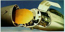 The AN/APG-66
is a pulse-doppler radar designed specifically for the F-16 Fighting
Falcon fighter aircraft. It was developed from Westinghouse's
WX-200 radar and is designed for operation with the Sparrow and
AMRAAM medium-range and the Sidewinder short- range missiles.
APG-66 uses a slotted planar-array antenna located in the aircraft's
nose and has four operating frequencies within the I/J band.
The modular system is configured to six Line-Replaceable Units
(LRUs), each with its own power supply. The LRUs consist of the
antenna, transmitter, low-power Radio Frequency (RF) unit, digital
signal processor, computer, and control panel. The AN/APG-66
is a pulse-doppler radar designed specifically for the F-16 Fighting
Falcon fighter aircraft. It was developed from Westinghouse's
WX-200 radar and is designed for operation with the Sparrow and
AMRAAM medium-range and the Sidewinder short- range missiles.
APG-66 uses a slotted planar-array antenna located in the aircraft's
nose and has four operating frequencies within the I/J band.
The modular system is configured to six Line-Replaceable Units
(LRUs), each with its own power supply. The LRUs consist of the
antenna, transmitter, low-power Radio Frequency (RF) unit, digital
signal processor, computer, and control panel.
The system has ten operating modes, which
are divided into air-to-air, air-to-surface display, and sub-modes.
The air-to- air modes are search and engagement. There are six
air-to-surface display modes (real beam ground map, expanded
real beam ground map, doppler beam- sharpening, beacon, and sea).
APG-66 also has two sub-modes, which are engagement and freeze.
In the search mode APG-66 performs uplook
and downlook scanning. The uplook mode uses a low Pulse Repetition
Frequency (PRF) for medium- and high-altitude target detection
in low clutter. Downlook uses medium PRF for target detection
in heavy clutter environments. The search mode also performs
search altitude display, which displays the relative altitude
of targets specified by the pilot.
Once a target is located via the search mode,
the engagement sub-mode can be used. Engagement allows the system
to use the AMRAAM , Sidewinder , and Sparrow missiles. When engaging
the Sidewinder , APG-66 sends slaving commands that slaves the
missile's seeker head to the radar's line-of-sight for increased
accuracy and missile lock-on speed. An Operational Capability
Upgrade (OCU) was developed to modify the APG-66 to use the AMRAAM
missile. The OCU is designed to provide the radar with the necessary
data link to perform mid-course updates of the missile. The Sparrow
's semi-active homing seeker is facilitated in the engagement
mode by a Continuous Wave Illuminator (CWI). The CWI also permits
APG-66 to be compatible with Skyflash and other missiles with
similar semi-active homing seekers.
Target acquisition can be manual or automatic
in the track mode. There are two main manual acquisition modes,
single-target track and situation awareness. The situation awareness
mode performs Track-While-Scan (TWS), allowing the pilot to continue
observing search targets while tracking a specific target. While
in this mode, the search area does not need to include the tracked
target's sector.
Four Air Combat Maneuvering (ACM) modes are
available for automatic target acquisition and tracking. In the
first ACM mode, a 20 x 20-deg Field Of View (FOV) is scanned.
This FOV is equal to that of the Head Up Display (HUD). Once
a target is detected, the radar performs automatic lock-on. The
second ACM mode's FOV is 10- x 40-deg, offering a tall window
that is perpendicular to the aircraft's longitudinal axis; this
proves especially useful in high-G maneuvering situations. A
boresight ACM mode is used for multiple aircraft engagement situations.
The boresight uses a pencil beam positioned at 0-deg azimuth
and minus 3-deg elevation to "spotlight" a target for
acquisition. This is especially useful in preventing engagement
of friendly aircraft. A slewable ACM mode allows the pilot to
rotate the 60- x 20-deg FOV. The automatic scan pattern gives
the pilot up to 4 sec of time. This mode is designed for use
when the aircraft is operating in the vertical plane or during
stern direction conversion.
The slant range measurement to a designated
surface location is generated by the Air-to-Ground Ranging (AGR)
mode. This real-time mode acts with the fire-control system to
guide missiles in air-to-ground combat. AGR is automatically
selected when the pilot selects the appropriate weapons deployment
mode.
Terrain in the aircraft's heading is displayed
via the real beam ground map mode. The radar provides the stabilized
image mainly as a navigational aid in ground target detection
and location. An extension of this mode is the expanded real
beam ground map. The expanded real beam ground map provides a
4:1 map expansion of the range around a point designated by the
pilot via the display screen's cursor.
Doppler Beam Sharpening (DBS) is available
to further enhance the higher resolution of the expanded real
beam ground map. This mode, which enhances the range and azimuth
resolution by 8:1, is only available from the expanded real beam
ground map mode.
In the Beacon mode the system performs navigational
fixing. It also delivers weapons relative to ground beacons and
can be used to locate friendly aircraft that are using air-to-air
beacons.
The high-clutter environment of the ocean
surface is countered in the sea mode. There are two sub modes
in the sea mode. The first sub-mode, Sea-1 is frequency-agile
and non- coherent to locate small targets in low sea states.
The second sub-mode, Sea-2, is fully coherent, with doppler discrimination
for the detection of moving surface crafts in high sea states.
The freeze sub-mode can only be accessed through
the air- to-ground display modes. It pauses the display and halts
all radar emissions as soon as the freeze command is received
via the controls. The aircraft's current position continues to
be shown on the frozen display. This mode is useful during penetration
operations against stationary surface targets when the aircraft
needs to prevent detection of its signals, yet continue to close
in on the target.
The system's displays include the control
panel, HUD, radar display, with all combat-critical controls
integrated into the throttle grip and side stick controller.
The modularity of the LRUs allow for shortened
Mean Time To Repair (MTTR) since they can simply be replaced,
involving no special tools or equipment. The MTTR has been demonstrated
to be 5 minutes, with 30 minutes for replacement of the antenna
unit. APG-66 has also demonstrated a Mean Time Between Failure
(MTBF) of 97 hours in service, but the manufacturers contend
that it has achieved 115 hours. A cockpit continuous self-test
system monitors for malfunctions. The manufacturers claim that
the system's Built-In-Test (BIT) routine can isolate up to 98%
of the faults to a particular LRU in the event of a malfunction.
A new version of the AN/APG-66, designated
the AN/APG-66(V)2 is being installed in F-16A/B aircraft as they
are modernized in the Midlife Update program. The equipment is
lighter and provides greater detection range and reliability
for the modernized F-16s.
|
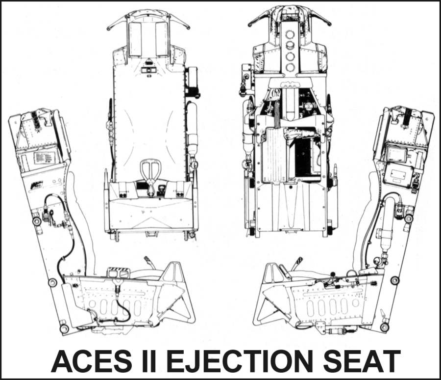
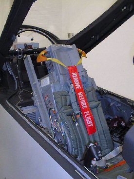
ACES II
|
|
The ACES II (Advanced Concept Ejection
Seat) is considered a smart seat since it senses the conditions of the ejection and selects
the proper deployment of the drogue and main parachutes to minimize
the forces on the occupant. The seat is a derivative of the Douglas
Escapac seat. conditions of the ejection and selects
the proper deployment of the drogue and main parachutes to minimize
the forces on the occupant. The seat is a derivative of the Douglas
Escapac seat.
Removal from the aircraft is by a three part pyrotechnic sequence.
A gun catapult provides the initial removal of the seat from
the aircraft. A rocket sustainer provides zero/zero capability
to the seat. To prevent the seat from tumbling when the aircraft
is in a roll maneuver or there is a center of gravity imbalance,
another (smaller) rocket called a STAPAC is attached to a gyroscope.
This senses the motion and attempts to keep the seat from spinning
by automaticly providing a correcting force.
Once clear of the aircraft, the pitot - static system on the
seat measures the conditions and selects one of three operating
modes depending on the conditions present at egress.
Mode 1 - Low speed (<250 knots) and low
altitude (<15 000 feet) operation.
The main parachute deploys as the seat clears the rails. Drogue
parachute remains undeployed to prevent line tangle.
Mode 2 - Moderate speed (250-650 knots) and
low altitude (<15 000 feet) operation.
Drogue parachute deploys as the seat leaves the rails. Main parachute
deploys 0.8 to 1.0 seconds after the drogue. Drogue chute is
then released to prevent line tangle.
Mode 3 - High speed (250-650 knots) and high
altitude (>15 000 feet) operation.
Drogue parachute deploys as the seat leaves the rails. The pitot
- static system senses the conditions and delays the main parachute
until mode 2 conditions are met. Then the main parachute deploys
after 0.8 to 1.0 seconds. Drogue chute is then released to prevent
line tangle. |
|
|
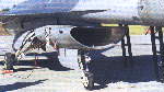 |
Landing Gear
Menasco hydraulically retractable type, nose
unit retracting aft and main units forward into fuselage. Nosewheel
is located aft of intake, to reduce the risk of foreign objects
being thrown into the engine during ground operation, and rotates
90o during retraction to lie horizontally under engine air intake
duct. Oleo-pneumatic struts in all units. Goodyear mainwheels
and brakes; Goodrich mainwheel tyres, size 25.5 × 8-14,
pressure 14.48 to 15.17 bars (210 to 220 lb/sq in) at T-O weight
less than 11,340 kg (25,000 lb). Steerable nosewheel with Goodrich
tyre, size 18 × 5.5-8, pressure 14.82 to 15.51 bars (215
to 225 lb/sq in) at T-O weights less than 11,340 kg (25,000 lb).
All but two main unit components interchangeable. Brake by wire
system on main gear, with Goodyear anti-skid units. Runway arrester
hook under rear fuselage. |
|
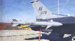 |
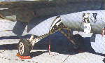 |
 |
|
|
Tail code markings |
Code Aircraft Unit, Location and Command
AK F-16 C/D, A/OA-10 354th FW, Eielson AFB, Alaska (PACAF)
AL F-16 C/D 187th FW, Montgomery, Ala. (ANG)
AV F-16 C/D 31st FW, Aviano AB, Italy (USAFE)
AZ F-16 A/B 162nd FW, Tucson, Ariz. (ANG)
CC F-16 C/D 27th FW, Cannon AFB, N.M. (ACC)
CO F-16 C/D 140th FW Buckley ANGB, Colo. (ANG)
DC F-16 C/D, C-21, C-22 113th FW, Andrews AFB, Md. (ANG)
FM F-16 A/B 482nd FW, Homestead AFB, Fla. (AFRES)
FS F-16 A/B 188th FW, Fort Smith, Ark. (ANG)
FW F-16 C/D 122nd FW, Fort Wayne, Ind. (ANG)
HA F-16 C/D 185th FG, Sioux City, Iowa (ANG)
HAFB F-16 Ogden ALC, Hill AFB, Utah (AFMC)
HI F-16 C/D 419th FW, Hill AFB, Utah (AFRES)
HL F-16 C/D 388th FW, Hill AFB, Utah (ACC)
IA F-16 C/D 132nd FW, Des Moines, Iowa (ANG)
LF F-16 A/B/C/D 56 FW, Luke AFB, Ariz. (AETC)
LR F-16 C/D 944th FW, Luke AFB, Ariz. (AFRES)
MI F-16 C/D, C-130E 127th FW, Selfridge ANGB, Mich. (ANG)
MO F-16 C/D, 366th WG, Mountain Home AFB, Idaho (ACC)
MY F-16 C/D, A/OA-10A, 347th FW, Moody AFB, Ga. (ACC)
NM F-16 C/D 150th FG, Kirtland AFB, N.M. (ANG) |
|
|
NY F-16 C/D 174th
FW, Hancock Field, N.Y. (ANG)
OH F-16 C/D 178th FW, Springfield, Ohio (ANG)
OH F-16 C/D 180th FW, Toledo, Ohio (ANG)
OK F-16 C/D 138th FG, Tulsa, Okla. (ANG)
OS F-16 C/D, A/OA-10A, 51st FW, Osan AB, Korea (PACAF)
OT F-16 A/C, USAFAWC, Eglin AFB, Fla. (ACC)
OT F-16 A/B/C/D 79th TEG, Eglin AFB, Fla. (AFMC)
PR F-16 A/B 156th FW, San Juan, Puerto Rico (ANG)
SA F-16 A/B 149th FG, Kelly AFB, Texas (ANG)
SC F-16 C/D 169th FG, McEntire ANGS, S.C. (ANG)
SD F-16 C/D 114th FG, Sioux Fall, S.D. (ANG)
SI F-16 C/D 183rd FW, Springfield, Ill. (ANG)
SP F-16 C/D, A/OA-10A, 52nd FW, Spangdahlem AB, Germany
(USAFE)
SW F-16 C/D 20th FW, Shaw AFB, S.C. (ACC)
TF F-16 C/D 301st FW, NAS JRB Fort Worth, Texas (AFRES)
TH F-16 C/D 181st FW, Terra Haute, Ind. (ANG)
VA F-16 C/D 192nd FG, Richmond, Va. (ANG)
VT F-16 C/D 158th FW, Burlington, Vt. (ANG)
WA F-16 A/B/C/D, 57th WG, Nellis AFB, Nev. (ACC)
WI F-16 C/D 115th FW, Madison, Wis. (ANG)
WP F-16 C/D 8th FW, Kunsan AB, Korea (PACAF)
WW F-16 C/D 35th FW, Misawa AB, Japan (PACAF) |
|
|
[ Home
] [ Info ] [ Armament
] [ Pictures ] [ Multimedia
] [ F-16XL ] [ Versions
] [ F-16 tour ]
[ Aerodynamics and G forces ] [ Advanced
fighter tactics ] [ News ]
[ Pilots glossary ] [ F-16
glossary ] [ Links ]
|